In industrial systems, check valves are critical for preventing backflow, protecting equipment, and maintaining process efficiency. However, improper installation can lead to premature wear, leaks, or even system failure. For engineers, mechanics, and technicians, understanding the technical nuances of check valve installation is essential. This guide breaks down key considerations, supported by industry standards and data, to ensure your valves perform reliably under demanding conditions.
Check valves are simple devices, but their effectiveness hinges on precise installation. Here’s what you need to prioritize:
Position check valves where they’re easily accessible for inspection and maintenance. For example, isolating a pipeline section during repairs requires valves to be strategically placed—ideally near pumps, elbows, or system branches. According to Rangeline, valves installed too close to bends or fittings risk turbulence, which accelerates wear.
Key Rule:
This minimizes turbulent flow, reducing stress on the valve disc and seat.
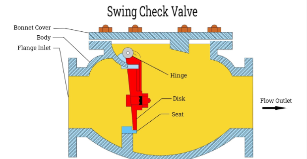
Check valves must align with the system’s flow direction. The valve body typically has an arrow indicating the correct orientation. Gravity-dependent valves (e.g., swing check valves) require vertical installation with flow moving upward. In contrast, silent spring-loaded check valves work in any orientation, including horizontal lines (Milwaukee Valve).
Pro Tip: After installation, verify the valve opens freely in the flow direction. A stuck disc can cause dangerous pressure surges.
The valve’s connection method impacts durability and leak resistance. Below is a comparison of common types:
| Connection Type | Best Applications | Pressure Rating | Ease of Maintenance |
|---|---|---|---|
| Threaded | Low-pressure systems (e.g., water lines) | Up to 150 psi | Simple, but prone to leaks if overtightened |
| Flanged | High-pressure, high-temperature systems | 150–2500 psi | Easy disassembly, requires precise alignment |
| Welded | Permanent, high-integrity systems (e.g., chemical plants) | 2500+ psi | Permanent; no disassembly possible |
Source: Rangeline, Allied Valve
Flanged connections are ideal for systems requiring frequent maintenance, while welded joints suit corrosive or high-pressure environments.
Follow these steps to ensure a secure, leak-free installation:
Valve materials must withstand the fluid’s chemical properties and temperature. For example:
Always cross-reference the valve’s pressure-temperature rating with the system’s operating conditions (Tameson).
Over-tightening threaded connections can strip threads or crack the valve body. For NPT threads, tighten until snug, then add 1/4 to 1/2 turn with a wrench.
Proper check valve installation isn’t just about following steps—it’s about understanding how design, placement, and materials impact long-term performance. By adhering to straight-pipe guidelines, choosing the right connection type, and verifying flow direction, you’ll minimize downtime and maintenance costs.
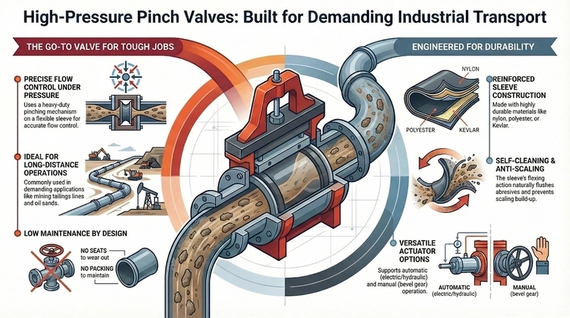
High pressure pinch valves, like PN16 pinch valve and class 150 pinch valve designs, involve a rugged and heavy-duty pinching mechanism in positioning the sleeve, resulting in an almost accurate and measurable flow of media. This kind of valve is popular and commonly used for long distance operations in mining tailings lines or oil sands, […]
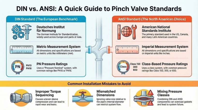
Understanding pinch valve dimensions and flanges ensures seamless integration into piping systems, particularly when choosing between DIN vs ANSI. The two are different but commonly used standards by organizations in engineering, manufacturing, and product design. DIN was developed in Germany but widely adopted across Europe and parts of Asia. Meanwhile, ANSI standards, which originate from […]
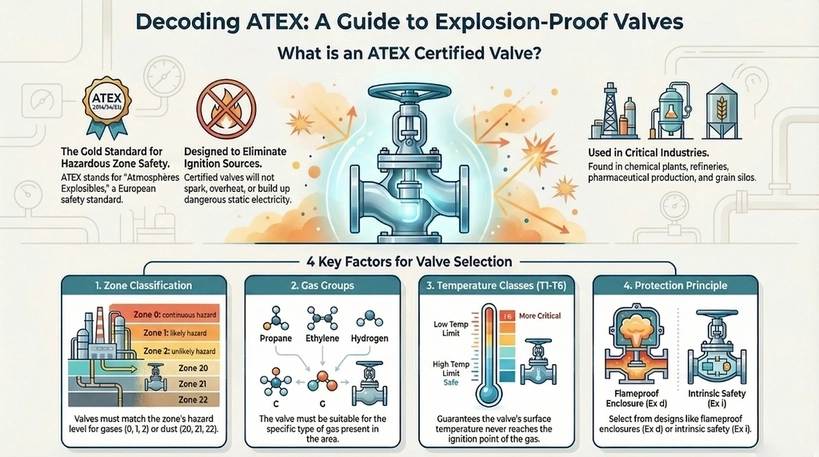
Selecting the appropriate explosion proof valve is essential for safety in industries that pose explosion risks. ATEX certified valves guarantee compliance with European standards, preventing ignition sources from heat, sparks, or static electricity. This blog explores key factors for choosing ATEX certified explosion proof valves that ensure overall operational safety, highlighting the entailed regulations and […]
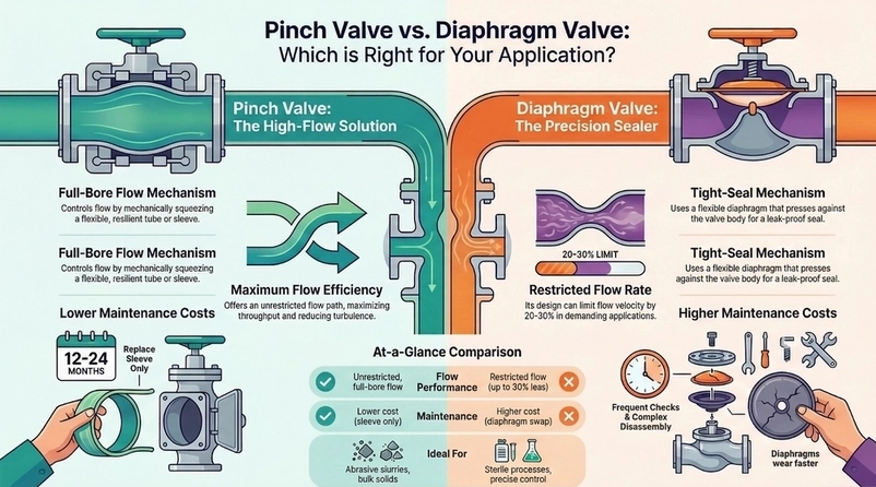
When handling abrasive or viscous media in industrial processes, the type of valve used can heavily affect the performance, efficiency, and overall user experience. In relation to this, two of the most common valve options are pinch and diaphragm valves. In this blog, we delve into the pinch valve vs diaphragm valve discussion, analyzing flow […]