P&ID (Piping and Instrumentation Diagram) valve symbols, also referred to as p and id valve symbols or P&ID valve symbols, are essential tools for engineers, EPC teams, and maintenance crews. They allow quick identification of valve type, actuation method, and fail-safe position directly on process diagrams.
This guide serves as a quick-reference library of the most common P&ID valve symbols, including 2-way, 3-way, and 4-way valves, actuator symbols, normally open (NO) / normally closed (NC) states, and end connections. A downloadable PDF cheat sheet is also included for easy offline reference.
If you’d like, you can send us your P&ID diagram, and we’ll recommend the optimal valve type, material, and end connection for your specific service conditions.
P&ID symbols are graphical representations used to depict the various components of a system, including valves, pumps, and control equipment.
These diagrams follow specific standards, such as ISO 14617 and ISA S5.1, which ensure that the symbols are universally understood.
When engineers and operators review these diagrams, they rely on the symbols to comprehend the system’s flow and operation quickly.
Each valve symbol provides crucial information about the type of valve and its function, whether it’s for controlling flow or acting as a safety device.
P&ID valve symbols provide engineers with a quick visual reference for identifying the type of valve used in a system.
These symbols help ensure that all stakeholders—such as engineers, operators, and maintenance teams—are on the same page when discussing system modifications or repairs.
Using standardized symbols reduces the risk of misunderstandings and errors during system operation or troubleshooting.
Additionally, the valve diagram provides clarity on how each valve interacts with other components in the system, from controlling pressure to regulating flow direction.
Whether it’s a check valve symbol, butterfly valve symbol, or flow control valve symbol, P&ID symbols make it easier to understand the entire process.
Various types of valves are used in industrial piping systems, each designed for specific functions. Below are the common valve types, their functions, and their corresponding symbols.
Credits to Assured Automation for all the Valve Symbol Images in this article.
| Valve Type | Functions | Valve Symbol |
| Ball Valve | On/off control, often in high-pressure systems. |  |
| Butterfly Valve | Flow regulation with minimal pressure drop. |  |
| Plug Valve | Plug valves are used for on/off control but offer a more compact design than ball valves. |  |
| Gate Valve | Flow isolation. |  |
| Globe Valve | Flow regulation. |  |
| Pinch Valve | Suitable for handling slurry or viscous fluids. |  |
| Needle Valve | Fine adjustment of flow rate. | 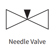 |
| Diaphragm Valve | Flow control for corrosive or viscous fluids. |  |
A 2-way valve has two ports—one for the inlet and one for the outlet—making it the most basic valve type.
All of the valve types listed above are 2-way inline valves, used to control flow either on/off or through throttling.
The valve’s function is generally determined by its actuation, such as manual, pneumatic, or electric.

3-way valves have three ports and are used to divert flow between two outlets or mix two flows. 3-way and 4-way valves, especially ball valves, may feature either a “T” or “L” port.
These diagrams show arrows indicating the flow path in the non-actuated state.

4-way valves have four ports, allowing more complex flow configurations.
Like 3-way valves, they can have “T” or “L” port configurations and may be represented with small arrows to depict the flow path in their non-actuated state.

| Valve Type | Functions | Valve Symbol |
| Check Valve | One-way flow to avoid reverse flow. |  |
| Pressure-Relief Valve | Protects systems from overpressure. |  |
| Pressure-Reducing Valve | Maintain system pressure at a set point. | 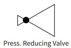 |
| Angle Valve | Change flow direction. | 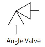 |
| Solenoid Valve | Electrical flow control. |  |
P&IDs also depict the valve’s state—whether normally open (NO), normally closed (NC), or bistable.
Normally open valves allow fluid to flow unless actuated to close, while normally closed valves do not allow flow until actuated to open.
Bistable valves maintain their last position even during power loss.
Actuators are essential in valve operations, as they determine how a valve is controlled. Each type of actuator plays a specific role in regulating the valve’s opening and closing mechanisms.
| Type | Functions |
| Manual (lever or handwheel) | Operates the valve manually, allowing the user to open or close it with physical effort. |
| Pneumatic Actuator (Diaphragm Type) | Uses compressed air to move a diaphragm, controlling valve operation. |
| Pneumatic Actuator (Rotary Piston Type) | Employs compressed air to rotate a piston, adjusting the valve’s position. |
| Electric Actuator | Utilizes electric power to operate the valve automatically, providing precise control. |
| Hydraulic Actuator | Operates via hydraulic fluid pressure, offering high force for valve operation. |

Fail-safe positions ensure that the valve moves to a predetermined state when an actuator fails or loses power, enhancing process safety.
| Fail-Safe Position | Function |
| Fail-Open (FO) | The valve remains or moves to an open position in case of actuator failure. |
| Fail-Closed (FC) | The valve stays or moves to a closed position during actuator failure. |
| Fail-in-Last-Position | The valve remains in its current position when the actuator fails, ensuring stability. |
End connections define how valves are attached to pipes and play a role in installation and maintenance.
| Type | Functions |
| Flanged | Allows the valve to be bolted between pipes, offering easy removal without cutting pipes. |
| Threaded | Uses threads to connect pipes to the valve, providing a semi-permanent solution. |
| Welded | Permanently connects the valve to pipes through welding, ensuring no leakage. |
| Socket Weld | Connects pipes to the valve using a hollow square socket, enabling a tight, permanent fit. |

Process lines transport different substances through the piping system, and various types of lines are used depending on the process requirements.
| Type | Meaning |
| Pipe | Basic process line for transporting fluids or gases through the system. |
| Thermally Insulated Pipe | Provides thermal insulation to maintain the fluid’s temperature within the pipe. |
| Jacketed Pipe | Features an outer layer to regulate temperature by heating or cooling the fluid. |
| Cooled or Heated Pipe | Uses an external system to cool or heat the fluid passing through the pipe. |
| Flexible Pipe or Tubing | Allows for movement and flexibility in connections, accommodating system expansion or vibration. |

In process control systems, different signal lines are used to communicate information between components, instruments, and control systems.
Each signal type has a distinct line style that helps identify the kind of signal being transmitted.
| Type | Functions | Symbol |
| Pneumatic Signal | Transmits signals using compressed air to control pneumatic instruments or actuators. | 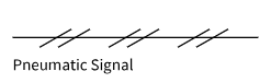 |
| Electronic/Electric Signal | Uses electrical currents or voltage to send data between components and the control system. |  |
| Hydraulic Signal | Utilizes fluid pressure to transmit control signals to hydraulic systems or actuators. |  |
| Guided Electromagnetic, Sonic or Fiber Optic Signal | Uses fiber optic cables or other media to transmit light-based or guided sonic signals. | 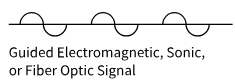 |
| Unguided Electromagnetic, Sonic or Wireless Signal | Sends signals wirelessly via electromagnetic waves, radio frequencies, or sonic signals. |  |
| Various Data Communication Signals | Transmits various forms of digital data through communication networks, enabling system control. |  |
Tag numbers in P&ID diagrams help identify instrumentation and its function within a control loop.
These are typically a combination of up to five letters followed by a unique loop number.
The letters represent the measured property, modifiers, passive and active functions, and additional details. Here’s a breakdown:
| Letter | Description | Examples |
| 1st Letter: Measured Property | Represents the property being measured. | F = Flow rate, P = Pressure, T = Temperature, L = Level |
| 2nd Letter: Modifier (Optional) | Indicates a specific condition of the measurement. | D = Differential, F = Ratio |
| 3rd Letter: Passive/Readout Function | Defines how the measurement is displayed or read. | A = Alarm, R = Record, I = Indicator, G = Gauge |
| 4th Letter: Active/Output Function | Indicates the action or control applied to the measurement. | C = Controller, T = Transmit, S = Switch, V = Valve |
| 5th Letter: Function Modifier (Optional) | Adds further specificity to the control or action. | H = High, L = Low, O = Open, C = Closed |
| Tag Number | Meaning | Description |
| FIC045 | Flow Indicating Controller in loop 045 | Measures flow rate, indicates, and controls flow |
| FT045 | Flow Transmitter in loop 045 | Measures and transmits flow data in the same loop |
| PIT102 | Pressure Indicating; Transmitter in loop 102 | Measures and transmits pressure, displays it locally |
| LAH200 | Level Alarm, High in loop 200 | Triggers an alarm when the level exceeds a high threshold |
| Common valve tag | Meaning | Typical scenario |
| FCV | Flow Control Valve | flow loop control |
| PCV | Pressure Control Valve | pressure control |
| TCV | Temperature Control Valve | temperature control |
| LV / LCV | Level (Control) Valve | tank level control |
| XV | On/Off Valve (often a shutdown/solenoid-actuated valve) | isolation/interlock |
| SDV / ESDV | Shutdown / Emergency shutdown valve | safety shutdown |
Yes, they are exactly the same. Both are abbreviations for Piping and Instrumentation Diagram, which engineers use to map out process flow, equipment, and control systems.
A standard dashed line typically represents an electronic or electrical signal. It shows how data or commands travel between instruments, whereas solid lines represent the actual physical process pipes.
These represent a valve’s “Fail-Safe” position if it loses power or air supply:
Follow the process flow (usually left to right). First, identify the main equipment shapes. Next, trace the connecting lines (solid for pipes, dashed for signals). Finally, read the alphanumeric tag numbers (like FCV for Flow Control Valve) to understand each instrument’s specific function.
Start with the base shape: two triangles pointing toward each other (like a bowtie) represent a generic valve. Modifications indicate the exact type (e.g., a circle in the center means a ball valve). A symbol attached to the top indicates the actuator type.
Valves are everywhere in industrial processes—controlling flow, isolating equipment, and protecting systems from overpressure. Yet for many engineers and technicians, the range of options can feel overwhelming. This guide covers the fundamentals of industrial valves, with a closer look at three widely used types: the lined valve, the pinch valve, and the stainless steel ball […]
Valve installation looks simple on paper—until you’re on-site, the flanges don’t line up, and the process fluid is waiting. In reality, poor installation is one of the leading causes of premature valve failure, leakage, and costly downtime. Whether you’re working with a lined valve, a strainer, or a pinch valve, the same fundamental rules apply. […]
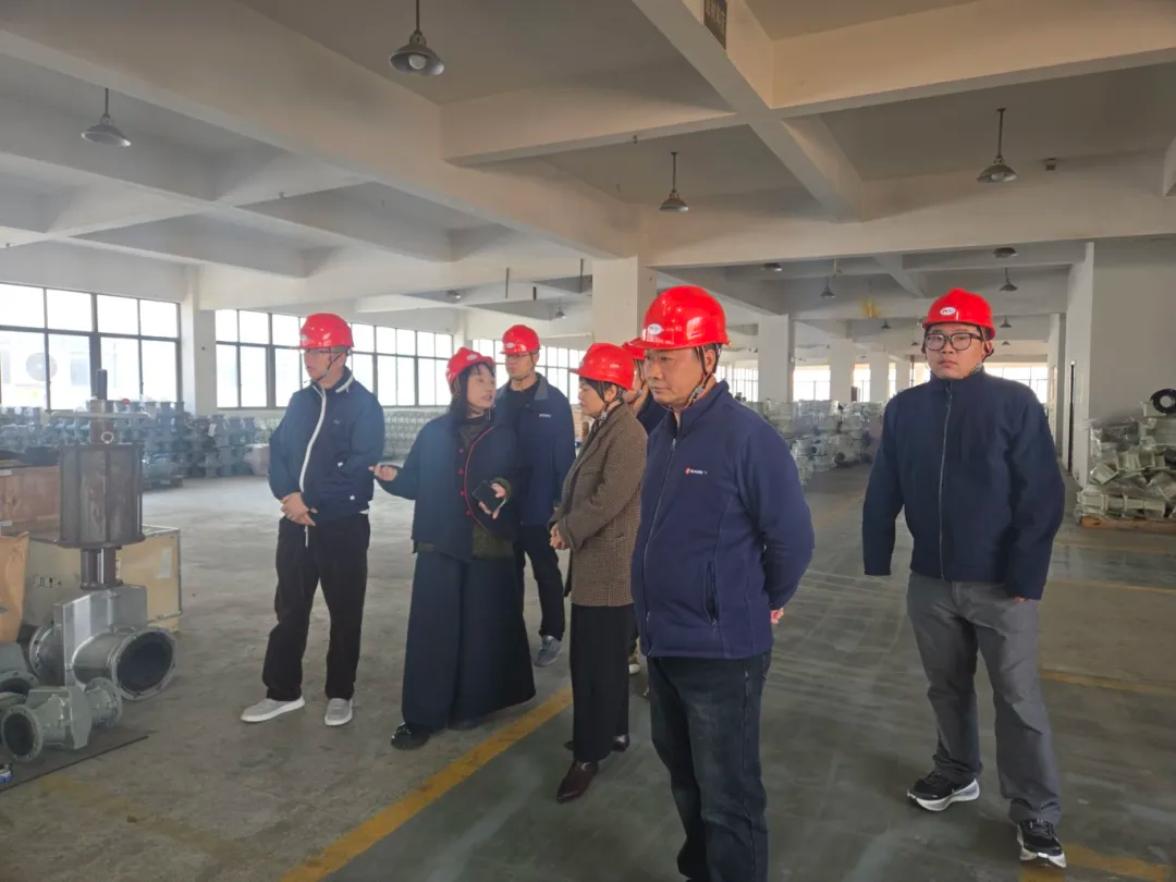
Lianke Valve Co., Ltd. has just wrapped up a busy and rewarding season of site visits. Over the past two weeks, we have hosted several groups of clients from home and abroad. They came with different goals, yet all turned their attention to Lianke’s manufacturing strength and technical expertise. Juhua Group, Quzhou In early March, […]
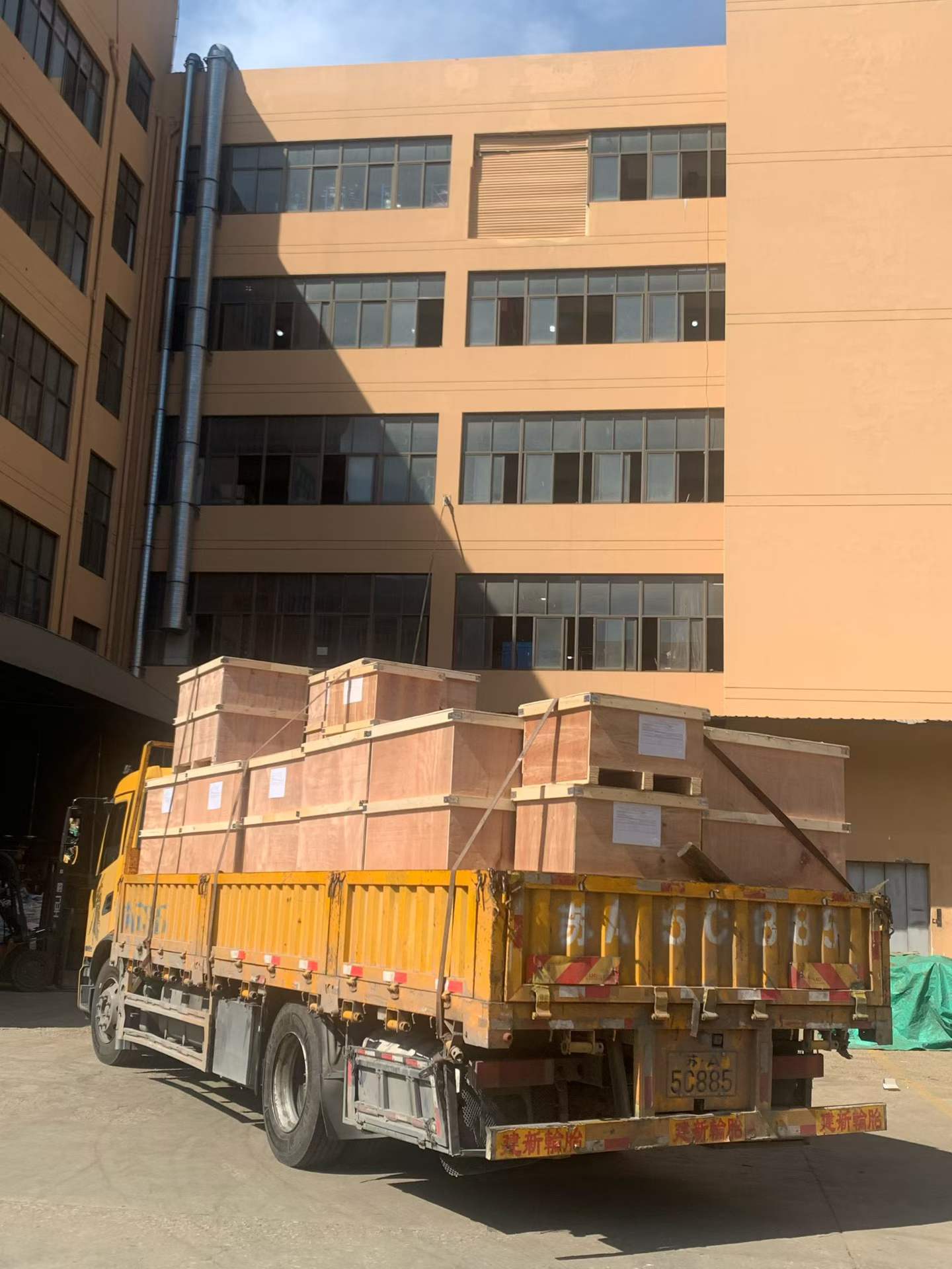
Recently, the production workshop at Lianke Valve has been bustling with activity, where production, inspection, packaging and other processes operate in efficient coordination. After rigorous multi-stage quality checks, a batch of high-quality pinch valve products has been packed and shipped, setting off for Russia. Export Product Case The pinch valves in this bulk shipment are […]