
Символы клапанов на схемах P&ID (Piping and Instrumentation Diagram), также называемые символами клапанов P&ID или символами клапанов P&ID, являются важными инструментами для инженеров, команд EPC и ремонтных бригад. Они позволяют быстро идентифицировать тип клапана, способ его управления и аварийное положение непосредственно на технологических схемах.
Данное руководство представляет собой справочный каталог наиболее распространенных обозначений клапанов на схемах P&ID, включая двухходовые, трехходовые и четырехходовые клапаны, обозначения приводов, нормально открытые (NO) / нормально закрытые (NC) состояния и концевые соединения. Для удобства использования в автономном режиме прилагается загружаемая шпаргалка в формате PDF.
При желании вы можете прислать нам свою технологическую схему (P&ID), и мы порекомендуем оптимальный тип клапана, материал и тип концевого соединения для ваших конкретных условий эксплуатации.
Символы P&ID — это графические представления, используемые для изображения различных компонентов системы, включая клапаны, насосы и контрольно-измерительное оборудование.
Эти диаграммы соответствуют определенным стандартам, таким как ISO 14617 и ISA S5.1, которые гарантируют универсальность понимания символов.
Когда инженеры и операторы просматривают эти схемы, они используют символы, чтобы быстро понять поток и работу системы.
Каждый символ клапана содержит важную информацию о типе клапана и его функции, будь то управление потоком или работа в качестве предохранительного устройства.
Символы клапанов P&ID предоставляют инженерам быструю визуальную справку для определения типа клапана, используемого в системе.
Эти символы помогают гарантировать, что все заинтересованные стороны, такие как инженеры, операторы и бригады по техническому обслуживанию, понимают друг друга при обсуждении модификаций или ремонтов системы.
Использование стандартизированных символов снижает риск возникновения недоразумений и ошибок при эксплуатации системы или устранении неисправностей.
Кроме того, схема клапанов наглядно показывает, как каждый клапан взаимодействует с другими компонентами системы, от управления давлением до регулирования направления потока.
Символы P&ID облегчают понимание всего процесса, будь то символ обратного клапана, символ поворотного затвора или символ клапана управления потоком.
В промышленных трубопроводных системах используются различные типы клапанов, каждый из которых предназначен для определенных функций. Ниже приведены распространенные типы клапанов, их функции и соответствующие им символы.
Кредиты для Гарантировано Автоматизация для Все изображения символов клапанов в этой статье.
| Тип клапана | Функции | Символ клапана |
| Шаровой клапан | Управление включением/выключением, часто в системах высокого давления. |  |
| Дроссельный клапан | Регулировка расхода с минимальным падением давления. |  |
| Запорный клапан | Пробковые краны используются для управления включением/выключением, но имеют более компактную конструкцию, чем шаровые краны. |  |
| Задвижка | Изоляция потока. |  |
| Шаровой клапан | Регулирование потока. |  |
| Пережимной клапан | Подходит для работы с пульпой и вязкими жидкостями. |  |
| Игольчатый клапан | Тонкая регулировка расхода. | 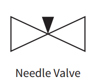 |
| Мембранный клапан | Регулирование расхода едких и вязких жидкостей. |  |
Двухходовой клапан имеет два порта — один для входа и один для выхода, что делает его самым простым типом клапана.
Все перечисленные выше типы клапанов представляют собой двухходовые линейные клапаны, используемые для управления потоком путем включения/выключения или дросселирования.
Функция клапана обычно определяется его приводом: ручным, пневматическим или электрическим.

Трехходовые клапаны имеют три порта и используются для перенаправления потока между двумя выходами или смешивания двух потоков. Трехходовые и четырехходовые клапаны, особенно шаровые краны, могут иметь порт «T» или «L».
На этих схемах показаны стрелки, указывающие путь потока в неактивированном состоянии.

Четырехходовые клапаны имеют четыре порта, что позволяет создавать более сложные конфигурации потока.
Как и трехходовые клапаны, они могут иметь конфигурации портов «T» или «L» и могут быть обозначены небольшими стрелками, указывающими путь потока в неактивированном состоянии.

| Тип клапана | Функции | Символ клапана |
| Обратный клапан | Односторонний поток, чтобы избежать обратного потока. |  |
| Клапан сброса давления | Защищает системы от избыточного давления. |  |
| Редукционный клапан | Поддерживайте давление в системе на заданном уровне. | 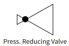 |
| Угловой клапан | Изменить направление потока. | 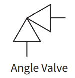 |
| Электромагнитный клапан | Управление электрическим потоком. |  |
На схемах трубопроводов и КИП также отображается состояние клапана — нормально открытый (НО), нормально закрытый (НЗ) или бистабильный.
Нормально открытые клапаны пропускают жидкость, пока не будут закрыты, в то время как нормально закрытые клапаны не пропускают жидкость, пока не будут открыты.
Бистабильные клапаны сохраняют свое последнее положение даже при отключении питания.
Приводы играют важную роль в работе клапанов, поскольку они определяют, как управляется клапан. Каждый тип привода играет определенную роль в регулировании механизмов открытия и закрытия клапана.
| Тип | Функции |
| Ручной (рычаг или маховик) | Управляет клапаном вручную, позволяя пользователю открывать или закрывать его с помощью физического усилия. |
| Пневматический привод (мембранного типа) | Использует сжатый воздух для перемещения диафрагмы, управляя работой клапана. |
| Пневматический привод (роторно-поршневого типа) | Использует сжатый воздух для вращения поршня, регулируя положение клапана. |
| Электрический привод | Использует электроэнергию для автоматического управления клапаном, обеспечивая точное управление. |
| Гидравлический привод | Работает за счет давления гидравлической жидкости, обеспечивая высокое усилие для срабатывания клапана. |

Положения безопасности гарантируют, что клапан перейдет в заданное состояние в случае отказа привода или потери питания, что повышает безопасность процесса.
| Положение безопасности | Функция |
| Fail-Open (FO) | В случае отказа привода клапан остается или перемещается в открытое положение. |
| Закрыто при отказе (FC) | При отказе привода клапан остается закрытым или перемещается в закрытое положение. |
| Неудачно занявший последнее место | При выходе из строя привода клапан остается в текущем положении, обеспечивая стабильность. |
Концевые соединения определяют способ крепления клапанов к трубам и играют важную роль при установке и обслуживании.
| Тип | Функции |
| Фланцевый | Позволяет закрепить клапан между трубами, что обеспечивает легкий демонтаж без разрезания труб. |
| Резьбовой | Для соединения труб с клапаном используется резьба, что обеспечивает полупостоянное решение. |
| Сварной | Обеспечивает постоянное соединение клапана с трубами посредством сварки, исключая возможность утечки. |
| Сварка враструб | Соединяет трубы с клапаном с помощью полого квадратного гнезда, обеспечивая плотное и постоянное соединение. |

Технологические линии транспортируют различные вещества по системе трубопроводов, и в зависимости от требований процесса используются различные типы линий.
| Тип | Значение |
| Трубка | Базовая технологическая линия для транспортировки жидкостей или газов через систему. |
| Теплоизолированная труба | Обеспечивает теплоизоляцию для поддержания температуры жидкости внутри трубы. |
| Труба в рубашке | Имеет внешний слой для регулирования температуры путем нагревания или охлаждения жидкости. |
| Охлаждаемая или нагреваемая труба | Использует внешнюю систему для охлаждения или нагрева жидкости, проходящей по трубе. |
| Гибкая труба или шланг | Обеспечивает подвижность и гибкость соединений, компенсируя расширение системы или вибрацию. |

В системах управления технологическими процессами для передачи информации между компонентами, приборами и системами управления используются различные сигнальные линии.
Каждый тип сигнала имеет свой стиль линии, который помогает определить вид передаваемого сигнала.
| Тип | Функции | Символ |
| Пневматический сигнал | Передает сигналы с помощью сжатого воздуха для управления пневматическими приборами или приводами. | 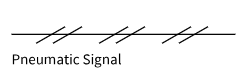 |
| Электронный/Электрический Сигнал | Использует электрические токи или напряжение для передачи данных между компонентами и системой управления. |  |
| Гидравлический сигнал | Использует давление жидкости для передачи сигналов управления гидравлическим системам или исполнительным механизмам. |  |
| Направляемый электромагнитный, звуковой или волоконно-оптический сигнал | Использует оптоволоконные кабели или другие носители для передачи световых или направленных звуковых сигналов. | 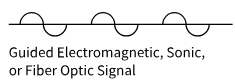 |
| Неуправляемый электромагнитный, звуковой или беспроводной сигнал | Передает сигналы по беспроводной связи с помощью электромагнитных волн, радиочастот или звуковых сигналов. |  |
| Различные сигналы передачи данных | Передает различные формы цифровых данных по сетям связи, обеспечивая управление системой. |  |
Номера меток на схемах P&ID помогают идентифицировать контрольно-измерительные приборы и их функции в контуре управления.
Обычно они представляют собой комбинацию из пяти букв, за которыми следует уникальный номер цикла.
Буквы представляют измеряемое свойство, модификаторы, пассивные и активные функции и дополнительные детали. Вот разбивка:
| Письмо | Описание | Примеры |
| 1-я буква: Измеренная собственность | Представляет измеряемое свойство. | F = Расход, P = Давление, T = Температура, L = Уровень |
| 2-я буква: Модификатор (необязательно) | Указывает на конкретное состояние измерения. | D = Дифференциал, F = Отношение |
| 3-я буква: Пассивная/считывающая функция | Определяет, как отображается или считывается измерение. | A = Сигнализация, R = Запись, I = Индикатор, G = Датчик |
| 4-я буква: Активная/выходная функция | Указывает действие или контроль, применяемый к измерению. | C = Контроллер, T = Передача, S = Переключатель, V = Клапан |
| 5-я буква: Модификатор функции (необязательно) | Добавляет дополнительную специфичность элементу управления или действию. | H = Высокий, L = Низкий, O = Открыто, C = Закрыто |
| Номер тега | Значение | Описание |
| ФИК045 | Контроллер индикации расхода в контуре 045 | Измеряет расход, показывает и контролирует поток |
| ФТ045 | Датчик расхода в петле 045 | Измеряет и передает данные о расходе в одном и том же цикле |
| ПИТ102 | Индикация давления; Передатчик в контуре 102 | Измеряет и передает давление, отображает его локально |
| ЛАХ200 | Сигнализация уровня, высокий в контуре 200 | Срабатывает сигнализация, когда уровень превышает верхний порог |
| Общая бирка клапана | Значение | Типичный сценарий |
| FCV | Регулирующий клапан потока | управление контуром потока |
| ПХВ | Клапан регулирования давления | контроль давления |
| TCV | Клапан регулирования температуры | контроль температуры |
| LV / LCV | Регулировочный клапан уровня | контроль уровня в резервуаре |
| XV | Запорный клапан (часто это запорный/электромагнитный клапан) | изоляция/блокировка |
| SDV / ESDV | Клапан аварийного отключения/остановки | аварийное отключение |
Да, это абсолютно одно и то же. Оба являются аббревиатурами от Piping and Instrumentation Diagram (схема трубопроводов и контрольно-измерительных приборов), которые инженеры используют для отображения технологических процессов, оборудования и систем управления.
Стандартная пунктирная линия обычно обозначает электронный или электрический сигнал. Она показывает, как данные или команды передаются между приборами, тогда как сплошные линии представляют собой фактические физические технологические трубопроводы.
Эти обозначения показывают “безопасное” положение клапана на случай отключения электропитания или подачи воздуха:
Следуйте технологической схеме (обычно слева направо). Сначала определите основные формы оборудования. Затем проследите соединительные линии (сплошные для труб, пунктирные для сигналов). Наконец, прочитайте буквенно-цифровые номера меток (например, FCV (для клапана регулирования потока), чтобы понять специфическую функцию каждого прибора.
Начнём с базовой формы: два треугольника, направленные друг к другу (как бабочка), представляют собой стандартный клапан. Модификации указывают на точный тип (например, круг в центре означает шаровой клапан). Символ, прикреплённый сверху, указывает на тип привода.

Valves are everywhere in industrial processes—controlling flow, isolating equipment, and protecting systems from overpressure. Yet for many engineers and technicians, the range of options can feel overwhelming. This guide covers the fundamentals of industrial valves, with a closer look at three widely used types: the lined valve, the pinch valve, and the stainless steel ball […]

Valve installation looks simple on paper—until you’re on-site, the flanges don’t line up, and the process fluid is waiting. In reality, poor installation is one of the leading causes of premature valve failure, leakage, and costly downtime. Whether you’re working with a lined valve, a strainer, or a pinch valve, the same fundamental rules apply. […]

Lianke Valve Co., Ltd. has just wrapped up a busy and rewarding season of site visits. Over the past two weeks, we have hosted several groups of clients from home and abroad. They came with different goals, yet all turned their attention to Lianke’s manufacturing strength and technical expertise. Juhua Group, Quzhou In early March, […]

Recently, the production workshop at Lianke Valve has been bustling with activity, where production, inspection, packaging and other processes operate in efficient coordination. After rigorous multi-stage quality checks, a batch of high-quality pinch valve products has been packed and shipped, setting off for Russia. Export Product Case The pinch valves in this bulk shipment are […]


